Introduction
Cellular telephones have revolutionized the communications arena, redefining how we perceive voice communications. Traditionally, cellular phones remained out of the hands of most consumers due to their high cost. As a result, cell phone carriers have invested time and resources into finding ways to give the systems higher capacity and thus lower cost. Cell systems are benefiting from this research and starting to develop into large-scale consumer products.
Today, cellular phones are truly consumer electronics devices with over 59 million subscribers. The Nokia Bowl and Qualcomm Stadium are further evidence of the idea that cell phones are consumer electronics devices. Since cell phones have ceased to be an exclusive status symbol of high-powered lawyers and are now in the hands of millions of consumers, they are now incredibly cost sensitive. Specifically, it is not the cost of the device that counts, but the cost of using the device. As a result, the cellular phone infrastructure is being optimized to allow calls to be placed as inexpensively and reliably as possible. Today, more than ever, cellular companies are looking for ways to bring down the call cost to attain even higher market penetration, especially in metropolitan areas.
In this report, we will begin by examining how cell phone systems work, paying close attention to details in system design that reduce cost and increase quality. After we have explained how cell phone systems work, we will examine the various cell phone systems in existence, examining the details of their operation and how that impacts the cost of using the system and the call quality on the system. Since the most important factor in cell phone airtime cost is the capacity, we will focus on issues related to capacity.
How Cell Phones Work
An Overview
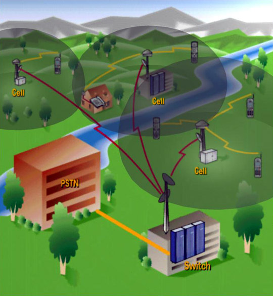
It is common knowledge that Cellular Phones (referred to as "cell" phones from here on) are wireless phones; however, many are confused about how a cell phone actually works. Essentially, cell phones use high-frequency radio signals to communicate with "cell towers" located throughout the calling area. Cell phones communicate in the frequency range of 806-890 MHz and 1850-1990 MHz for the newly allocated "PCS" frequency range.
When the user wants to make a call, the cell phone sends a message to the tower, asking to be connected to a given telephone number. If the tower has sufficient resources to grant the request, a device called a "switch" patches the cell phone’s signal throughout to a channel on the "public switched telephone network" (otherwise known as the PSTN). This call now takes up a wireless channel as well as a PSTN channel that will be held open until the call is completed. The following figure illustrates this process.

Given this simple description of how cell phones work, we will add technical details about various facets of cell phone systems throughout the remainder of this section.
Cells
As the name implies, cell phone systems are made up of many small "cells." Each cell in a cell phone system represents the area served by one cell phone tower. The concept of cells is key behind the success of cell phones because by spacing many cells fairly close to each other, the cell phones may broadcast at very low power levels (typically 200mW – 1W, depending on system). Since the cell phones may broadcast at low power levels, they use small transmitters and small batteries, and thus are able to fit in a shirt pocket, unlike amateur radios can occupy a tabletop.
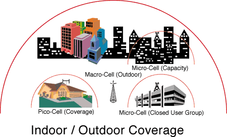
Cells are typically spaced around 1-2 miles apart but can be spaced up to 20 miles apart in rural areas. In loaded areas or areas with many obstacles (such as tall buildings), the cell sites may be spaced closer together. Some technologies, like PCS, require closer cell spacing due to their higher frequency and lower power operation. Additionally, buildings interfere with cell signals coming from outside, so many buildings have their own "microcell." The Kingdome and New York subway are two examples of where microcells are used. Microcells may also be used to increase overall capacity within a heavily populated area such as a city’s core downtown area. In fact, homes may have "picocells" connected to the home’s PSTN connection to allow the cell phone to be used as a cordless phone. An example of typical microcell and picocell environments is pictured in the following figure.
Encoding and Multiplexing
Overview
With thousands of cellular phone calls going on at any given time within a city, it certainly would not work for everyone to talk on the came channel at once (as in CB and short-wave radios). Therefore, several different techniques were developed by cell phone manufacturers to split up the available bandwidth into many channels each capable of supporting one conversation. The following sections will discuss each technology and how it works.
Analog vs. Digital
While the distinction between analog and digital encoding is probably obvious to most readers, a short discussion is included for those who are not. Essentially, analog broadcasts audio as a series of continuously changing, voltage levels representing the amplitude of the voice conversation. When sent on the cell phone network using the standard frequency modulation (meaning voltage levels translate into frequency shifts) into channels separated by 30 kHz, we find that the amplitude can be effectively transmitted at 15 kHz due to Nyquist limitations.
Instead of sending data as various voltage levels, a digital signal quantizes the voltage levels into a number of bins (typically 28 or 256 representing an 8-bit encoding). These bins are encoded as a binary number and sent as a series of ones and zeros. This allows for digital compression in the encoding stage enabling voice to be sent at as little as 8000 bits per second.
FDMA
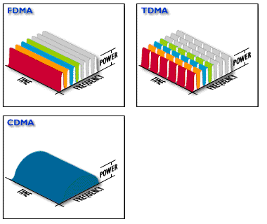
FDMA stands for "frequency division multiple access" and, though it could be used for digital systems, is exclusively used on all analog cellular systems. Essentially, FDMA splits the allocated spectrum into many channels. In current analog cell systems, each channel is 30 kHz. When a FDMA cell phone establishes a call, it reserves the frequency channel for the entire duration of the call. The voice data is modulated into this channel’s frequency band (using frequency modulation) and sent over the airwaves. At the receiver, the information is recovered using a band-pass filter. The phone uses a common digital control channel to acquire channels.
FDMA systems are the least efficient cellular system since each analog channel can only be used by one user at a time. Not only are these channels larger than necessary given modern digital voice compression, but they are also wasted whenever there is silence during the cell phone conversation. Analog signals are also especially susceptible to noise – and there is no way to filter it out. Given the nature of the signal, analog cell phones must use higher power (between 1 and 3 watts) to get acceptable call quality. Given these shortcomings, it is easy to see why FDMA is being replaced by newer digital techniques.
TDMA
TDMA stands for "time division multiple access." TDMA builds on FDMA by dividing conversations by frequency and time. Since digital compression allows voice to be sent at well under 10 kilobits per second (equivalent to 10 kHz), TDMA fits three digital conversations into a FDMA channel (which is 30 kHz). By sampling a person’s voice for, say 30 milliseconds, then transmitting it in 10 milliseconds; the system is able to offer 3 timeslots per channel in a round-robin fashion. This technique allows compatibility with FDMA while enabling digital services and easily boosting system capacity by three times.
While TDMA is a good digital system, it is still somewhat inefficient since it has no flexibility for varying digital data rates (high quality voice, low quality voice, pager traffic) and has no accommodations for silence in a telephone conversation. In other words, once a call is initiated, the channel/timeslot pair belongs to the phone for the duration of the call. TDMA also requires strict signaling and timeslot synchronization. A digital control channel provides synchronization functionality as well as adding voice mail and message notification. Due to the digital signal, TDMA phones need only broadcast at 600 miliwatts.
CDMA
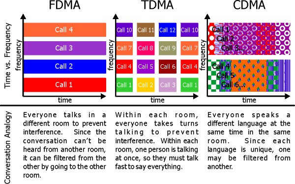
CDMA stands for "code division multiple access" and is both the most interesting and the hardest to implement multiplexing method. CDMA has been likened to a party: When everyone talks at once, no one can be understood, however, if everyone speaks a different language, then they can be understood. CDMA systems have no channels, but instead encodes each call as a coded sequence across the entire frequency spectrum. Each conversation is modulated, in the digital domain, with a unique code (called a pseudo-noise code) that makes it distinguishable from the other calls in the frequency spectrum. Using a correlation calculation and the code the call was encoded with, the digital audio signal can be extracted from the other signals being broadcast by other phones on the network. From the perspective of one call, upon extracting the signal, everything else appears to be low-level noise. As long as there is sufficient separation between the codes (said to be mutually orthogonal), the noise level will be low enough to recover the digital signal. Each signal is not, in fact, spread across the whole spectrum (12.5 MHz for traditional cellular or 60 MHz in PCS cellular), but is spread across 1.25 MHz "pass-bands."
CDMA systems are the latest technology on the market and are already eclipsing TDMA in terms of cost and call quality. Since CDMA offers far greater capacity and variable data rates depending on the audio activity, many more users can be fit into a given frequency spectrum and higher audio quality can be provide. The current CDMA systems boast at least three times the capacity of TDMA and GSM systems. The fact that CDMA shares frequencies with neighboring cell towers allows for easier installation of extra capacity, since extra capacity can be achieved by simply adding extra cell sites and shrinking power levels of nearby sites. CDMA technology also allows lower cell phone power levels (200 miliwatts) since the modulation techniques expect to deal with noise and are well suited to weaker signals. The downside to CDMA is the complexity of deciphering and extracting the received signals, especially if there are multiple signal paths (reflections) between the phone and the cell tower (called multipath interference). As a result, CDMA phones are twice as expensive as TDMA phones and CDMA cell site equipment is 3-4 times the price of TDMA equivalents.
An animated picture roughly demonstrating the differences between these strategies follows.
This is another figure demonstrating the differences between FDMA, TDMA, and CDMA.
GSM
GSM stands for "Global System for Mobile Communications." GSM is mostly a European system and is largely unused in the US. GSM is interesting in that it uses a modified and far more efficient version of TDMA. GSM keeps the idea of timeslots and frequency channels, but corrects several major shortcomings. Since the GSM timeslots are smaller than TDMA, they hold less data but allow for data rates starting at 300 bits per second. Thus, a call can use as many timeslots as necessary up to a limit of 13 kilobits per second. When a call is inactive (silence) or may be compressed more, fewer timeslots are used. To facilitate filling in gaps left by unused timeslots, calls do "frequency hopping" in GSM. This means that calls will jump between channels and timeslots to maximize the system’s usage. A control channel is used to communicate the frequency hopping and other information between the cell tower and the phone. To compare with the other systems, it should be noted that GSM requires 1 Watt of output power from the phone.
Call Handoff
It is apparent that cells must somehow overlap, and when a user travels between cells, one cell must hand the call off to the other cell. The cells must also not interfere with each other. This is accomplished by giving each cell a slightly different chunk of the frequency spectrum (note that CDMA does not do this) and by measuring power levels. When the power level of the user begins to fade, the cell tower determines which cell is the closest cell. Upon finding this information, the current cell tower sends an over-the-air message to the new cell tower and to the cell phone. At this point, the new cell tower picks up the call and the old one drops the call as the cell phone switches frequencies. This type of handoff is called a "hard handoff" since the audio feed is lost for between 10 milliseconds and 100 milliseconds while the new tower picks up the signal. Often these "hard" handoffs fail when the new tower tries to pick the call up, leading to frequent dropped calls.
In most systems, each cell tower typically receives a 1.8 MHz frequency spectrum. In normal cellular systems that have a 12.5 MHz spectrum (not the high-band PCS systems that have more bandwidth), this allows for 7 cells before cells have to reuse frequencies. Generally, there are 1-2 cells and 10-20 miles separating cells using the same frequency in order to minimize interference.
A discussion of call handoff is not complete without CDMA technology. Since CDMA uses the entire spectrum available, there is no real distinction between cells in terms of frequency use. Since each call is scattered across a whole 1.25 MHz pass band in CDMA, every cell tower can access the whole 12.5 MHz spectrum (60 MHz in a PCS system). This means that there is no necessity to change frequencies during a handoff since everyone is using the same frequencies. Therefore, two cell towers intercept the signal where the cells overlap. This means no sudden switch, since this handoff (called a "soft handoff") is actually handled in the switch, changing from one weaker audio feed to a stronger audio feed. This technique removes the loud "pop" associated with normal "hard" handoffs and greatly reduces problems with dropped calls. The soft handoff concept is pictured below.
Security
One of the largest problems in wireless communication is security. There are two worries: Other people listening into phone calls and other people illegally billing time to a user’s account (called "phone cloning").
Unfortunately, analog phones transmit in plain FM, and provide no security. For instance, a few years ago, Newt Gingrich had a cell phone conversation taped by someone using a simple police scanner, which is designed to receive police activity on the CB frequencies. Since analog phones have such weak security, the architects of digital technology designed digital phones with much more robust security.
Digital phones employ encryption to secure the phone and the conversation. Encryption is used in TDMA and CDMA to make sure that it is almost impossible to "latch" onto a conversation. The encryption works by picking a key that is used in an equation that compresses the audio. The encrypted key is sent to the cell tower so the cell tower knows how to decode the conversation. Therefore, even if the person with the scanner finds the channel and time slice you are using, they would need to find the encryption code to make sense of the signal. It is also important to mention that CDMA also uses its modulation code to provide increased security, resulting in over four billion possible encryption codes. Cell phones also must be protected from cloning. By encrypting the cell phone number and related information when sending the information to the switch, cloning is prevented.
Switching
Overview
When a user places a call on a cell phone, the system must figure out how to route the call to the PSTN. Additionally, when someone calls the cell phone, the system must figure what cell the user is in. This section describes how this is done.
Finding the user
Whenever you turn your cell phone on, the phone sends its identification to the cell phone tower. This includes the "MIN" (mobile identification number, usually the phone number) and the "ESN" (electronic serial number). The cell tower forwards this information to a centrally located switch via special leased phone lines that connect a switch to many cell sites (T-1 lines are often used). When the switch gets this information, it forwards it to any higher level switches.
Connecting the call
Whenever a call comes in, it will come to the switch that serves the exchange (the exchange is the 555 in (206) 555-1212). This top-level switch will pass that call onto any lower level switches, if there is one, although there usually is not. When the call is passed to the lowest level switch, it checks to make sure the phone is still registered (it is turned on and in range). If it is registered, the phone is notified via the signaling channel and the phone begins ringing. When the user chooses to accept the call, the switch establishes the voice channel and the call begins.
Roaming
Roaming was one of the most challenging issues the cell phone industry faced. The goal was simple: a phone could be used anywhere in the US or the world where compatible technology is used. The difficult part is getting various systems to communicate and pass routing and billing information to each other.
When a user turns his or her cell phone on in a roaming area, the cell phone identifies itself to the switch. When the switch looks up the information and discovers it is not a local phone, it will attempt to find the "home" switch based on the exchange. When it locates the home switch, it will determine if roaming is possible. If roaming is possible, the switch (referred to here as the "roaming switch") sets up a "Visitor Location Register" (VLR) registering the phone in the locality. The home switch will also be notified about the change so that it can route calls to the switch in the roaming location. Outbound calls are handled through the roaming switch as they would be handled if the user were at home. Incoming calls are routed from the home switch to the roaming switch after sending a message to the roaming switch requesting a "temporary local directory number" (TLDN). This TLDN will be used to make a connection from the home switch to the roaming switch across the PSTN. Finally, whenever the roaming phone is turned off, the phone is unregistered with the roaming switch and the home switch is notified. The process of registering the phone and notifying the home switch takes 2 seconds.
Wireless Data
Overview
In modern times, we depend on e-mail and on the World Wide Web. We have access to these resources at home and at the offices, and we would like to use these resources while traveling. This is the goal that "wireless data" hopes to accomplish. In the following section, we will discuss various types of wireless data systems that run on top of cellular networks. Systems that run on other systems, such as ricochet, which runs on the pager network, will not be discussed.
Analog modems
Analog modems are the simplest type of wireless data. Analog modems work on any cellular system by simply encoding the digital data as audio signals. Analog cellular modems make the same squealing sounds as an ordinary desktop computer’s analog modem, but operate at far slower speeds. On an analog modem, these modems typically average between 4800 to 9600 bits per second. This is slower than the maximum possible rate because of the inefficiency of converting digital to analog. It should also be noted that digital cell systems do not support analog modems since their data compression would damage the analog modem signal, preventing it from being decoded by the receiving modem.
Packet Data (CDPD over IS-136 and AMPS networks)
By using some of the channels of the TDMA or FDMA (IS-136 and AMPS standards) network as large aggregated digital data lines, packetized digital data may be sent over this line. CDPD describes how every cell phone on the network may insert packets on this shared data channel without causing collisions, which would happen if two packets were sent at the same time by two different phones. CDPD is useful since it runs on top of old FDMA systems as well as newer TDMA systems and offers a 19.2 kilobits per second data rate. Using a TDMA system, the CDPD protocol can be scaled by adding more frequency channels.
GSM
GSM uses an intriguing method to send data. By simply sending computer data as it would send voice data, GSM allows every phone to be "data enabled." Since the GSM network is already a packet network of sorts because of its frequency hopping, it requires no additional hardware to support data. GSM allows data rates in multiples of 300 bits per second, up to 64 kilobits per second.
Determining capacity
The cell towers themselves are perhaps the most costly part of operating a cellular phone network. Cell towers are exposed to environmental hazards, such as weather, wildlife, and vandalism. The quality of service obtainable from cell towers varies widely depending upon interference from other sources such as radio towers, interference from other cell towers, and obstacles such as tall buildings.
Also taken into account is the relative power consumption of each tower. If each tower consumes a substantial amount of power, it would not be cost effective to put up many towers in a small area. The density of cell towers must offset their power consumption.
Finally, the users themselves demand a high quality of service. In densely populated urban areas, users will complain if a tower fails and an entire neighborhood loses cell phone coverage. In this case, it might be cost effective to put in more towers that offer higher bandwidth or make some towers redundant as a backup for failure.
Unlike the user devices, which the users maintain themselves, service providers must setup and operate the towers. Because users demand extensive coverage and the ability to roam, the areas serviced by cell towers must therefore cover a large and extensive area. However, cell towers are limited in their range and power; consequently, service providers must determine the optimal mix of power consumption, quality of service, and number of users per tower in order to optimize placement.
With this in mind, there are a number of different algorithms, which approximately determine the number of users each tower can handle. For FDMA and TDMA systems, this is clearly a more or less linear function. In the case of an FDMA system, the amount of noise from other sources and the amount of power transmitted determine the number of discrete frequency bands into which the total transmission band can be divided. Although fewer bands do not necessarily mean clearer service, fewer bands generally means less distortion from noise. The number of users is equal to the number of frequency bands, since each user receives a band for the duration of the call.
In the case of TDMA systems, noise and power determine the number of frequency bands as well as the rate at which users may be swapped. The number of users each tower can handle is a multiple of the number that can be handled in FDMA. This multiple is simply the number of calls that may be swapped round-robin fashion.
The number of callers handled by a CDMA tower is much more complex to determine because the power output of a CDMA tower is not constant. As a result, the number of users a CDMA tower can handle depends upon the data rate, the spreading bandwidth of each tower, and the targeted signal to noise ratio.
A simple equation from http://www.cdg.org/a_ross/CDMARevolution.html, given below, is used to model this behavior.

In this equation, W is the spreading bandwidth given in decibels and is a specified multiple of R, the data rate. A greater spreading bandwidth means a greater ability to accommodate users far away from the tower. The rate set used for this model as specified by IS-95A CDMA sets the data rate at 9.6 kbps.
Eb/N0 is the signal to noise ratio. I0 is a correction factor that takes into account interference from other towers. For the purposes of this experiment, I0 is taken to be zero. The signal to noise ratio is varied to see the effects on the user capacity.
As seen in the figure below, the number of possible users varies exponentially with the signal to noise ratio.
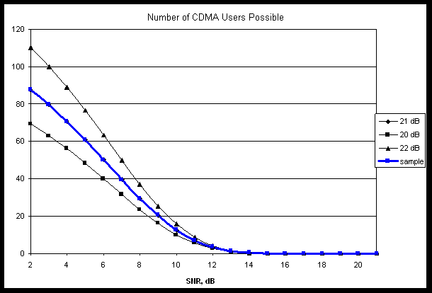
The tower can dynamically increase or decrease its user capacity depending upon variations in signal to noise ratio or spreading bandwidth.
Future
Overview
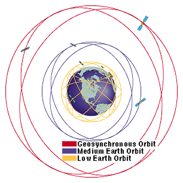
As cellular systems reach maturity, many are looking to the future. While the PCS frequencies (1800 MHz – 2000 MHz) are still being built out, the next generation of cellular communication is being launched. To provide true homogeneous worldwide wireless coverage with no gaps, LEO (low earth orbit) satellites are being used. These LEO satellites orbit the earth in high speed, low altitude orbits with an orbital time of 70-90 minutes and an altitude of 400 – 700 miles. LEO’s provide small coverage cells around the size Washington state. Since LEO’s are not geosynchronous, they are forced to fly complete orbits, and thus many must exist to guarantee every area is covered by at least one satellite at all times. Therefore, call handoff is executed when the satellite moves, not when the person moves as it is with ground-based cellular systems.
A figure outlining the different orbits follows.
Satellite Systems
Iridium
Motorola has just launched the last satellite in the Iridium system, a LEO system consisting of 66 satellites with 6 in-orbit spares. Iridium satellites have an orbital altitude of 485 miles and weigh 1,500 pounds each. Iridium will allow a person to place a call anywhere in the world using a device slightly larger than a small hand-held cell phone. Iridium will begin service this summer.
Globalstar
Globalstar is a CDMA system headed up by Qualcomm. This system will have 48 satellites with 8 in-orbit spares. Each satellite will weigh 1000 pounds and will orbit at 880 miles. Again, this system will use phones that are just slightly larger than today’s conventional cell phones and allow calls to be placed anywhere in the world. Globalstar expects to have the system launched in 1998 and will begin to provide service in 1999.
Teledesic
Teledesic is the most promising and furthest off of the LEO systems. Teledesic is a partnership of many large players in this industry, including Motorola, Microsoft, Boeing, Nextel, and Matra Marconi, with Motorola being the prime contractor. Teledesic will use 288 satellites flying at an altitude of less than 800 miles. This means that Teledesic will have five times the satellites as the other systems and will fly lower than the other systems. This translates into more bandwidth per region (smaller coverage area per satellite) and smaller cellular phone devices (lower power since satellites are closer). Teledesic also plans to provide high-speed data access, starting at 64 megabits per second. Teledesic has begun development of their satellites, and expects to start service in 2003.
Other Future Systems
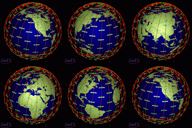
There are several other future cellular systems planned. One of these systems involves sending unmanned blimps high above the city at 70,000 feet. These blimps would provide cellular voice and data service to a city, with service similar to what LEO’s provide. Another plan is to have high-flying (flying at a 52,000 foot altitude) unmanned solar-powered aircraft that would continually fly west to east across the US and provide LEO like cellular voice and data service. Though these other ideas appear farfetched, if they are implemented, they will provide more competition and thus lower prices.
Below is a figure illustrating this concept.
Conclusions
Cellular phone customers clearly have many different service choices that they did not have several years ago. Furthermore, it is inevitable that as the technology evolves, the quality of service will increase and the equipment cost will decrease. Older technologies will become cheaper as newer technologies are introduced to the global market.
The analysis in the "Cost Factors" section has demonstrated on a theoretical level how newer technologies such as CDMA can give finer control over the cost per user of providing service by regulating user capacity as a function of signal noise. Although limiting factors still exist, the number of frequency bands allocated in the total frequency range no longer fixes the user capacity. This allows service providers to target a more optimum quality of service and user load, which benefits both user and service provider.
By eliminating the requirement that towers transmit at constant power, CDMA systems can better optimize their utilization. Other technologies such as satellite networks and GSM improve their utilization by similarly exploiting their advances over standard FDMA and TDMA networks. The result is that newer cellular networks will be intelligent enough to improve their utilization and quality of service, which in turn benefits the user.
Bibliography
http://kbs.cs.tu-berlin.de/~jutta/gsm/js-intro.html http://mars.mcs.kent.edu/ksuthesis/node15.html http://mars.mcs.kent.edu/ksuthesis/node16.html http://www-dse.doc.ic.ac.uk/~nd/surprise_96/journal/vol1/pr4/article1.html http://www.airtouch.com/ http://www.attws.com/ http://www.cdg.org/a_ross/ http://www.cdg.org/cdma_tech.html http://www.ee.surrey.ac.uk/Personal/L.Wood/constellations/ http://www.ericsson.com/ http://www.globalstar.com/ http://www.iridium.com/ http://www.mot.com/CNSS/CIG/Help/faqindex.html http://www.nacn.com/ http://www.nokia.com/ http://www.philipsconsumer.com/glossary.html http://www.qualcomm.com/ http://www.realtime-info.be/encyc/techno/terms/terms.htm http://www.sprintpcs.com/ http://www.teledesic.com/ http://www.uwcc.org/ http://www.webproforum.com/uwc/ http://www.wow-com.com/consumer/